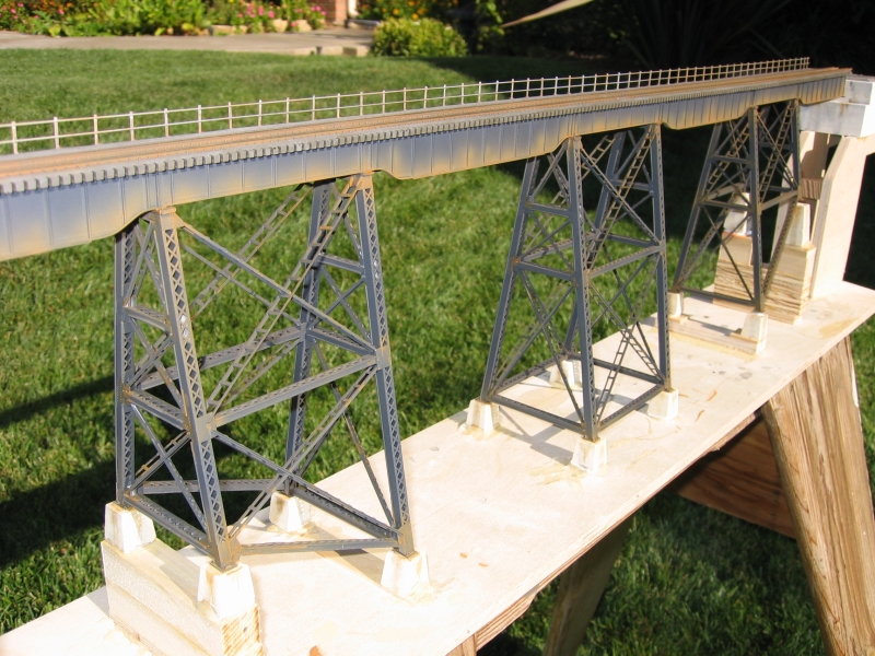
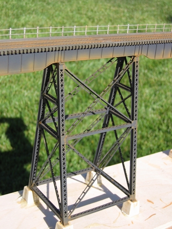
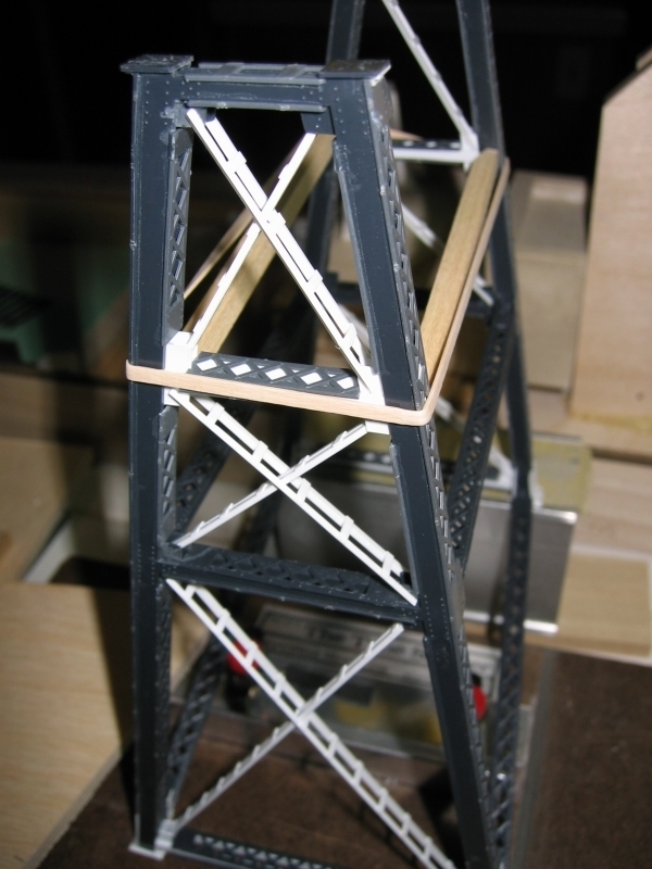
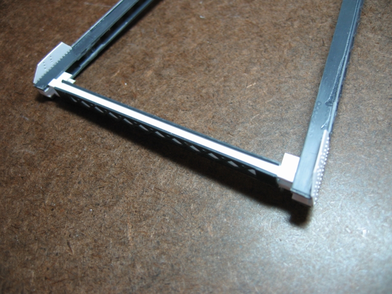
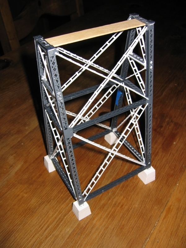
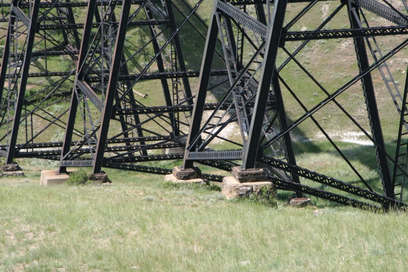
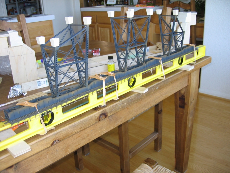
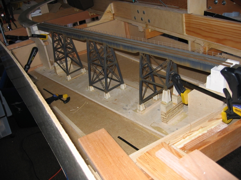
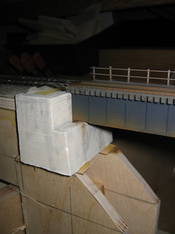
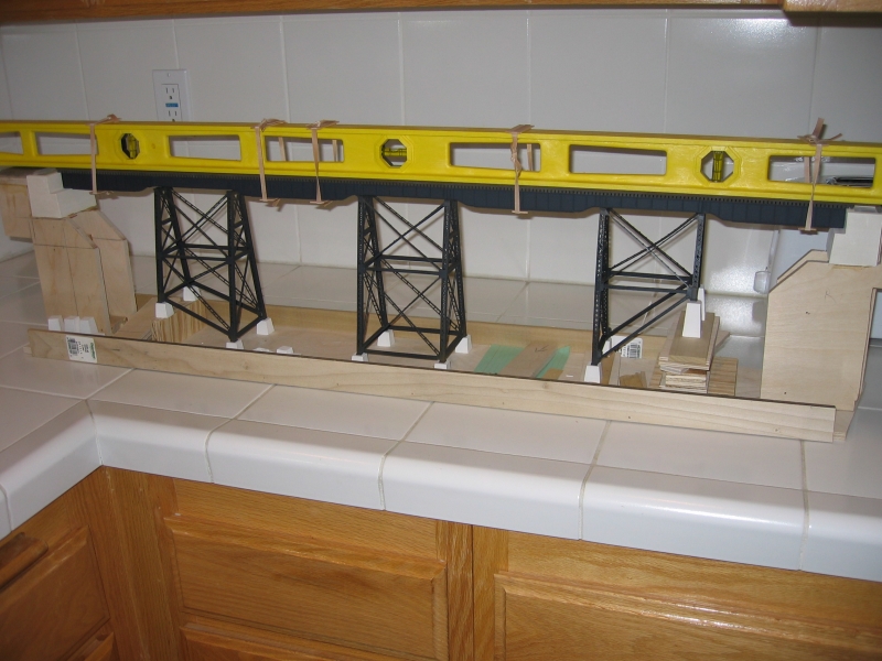
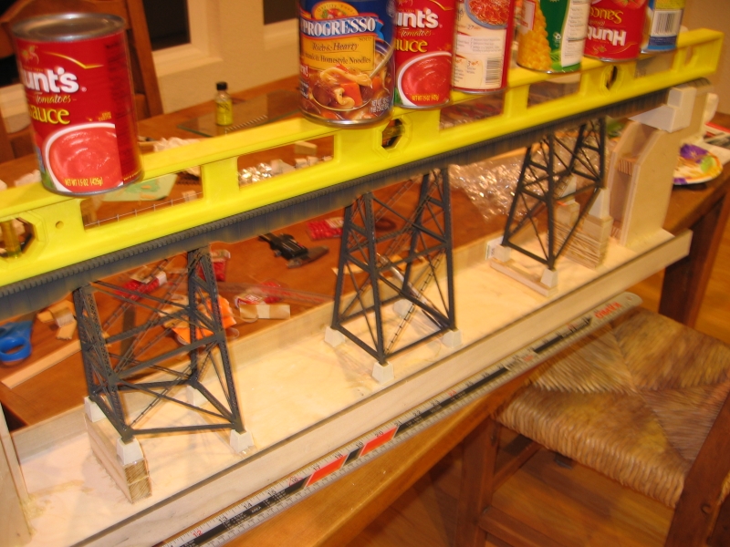
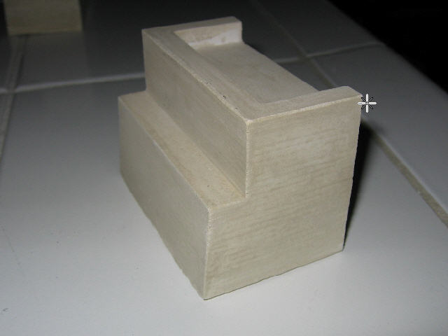
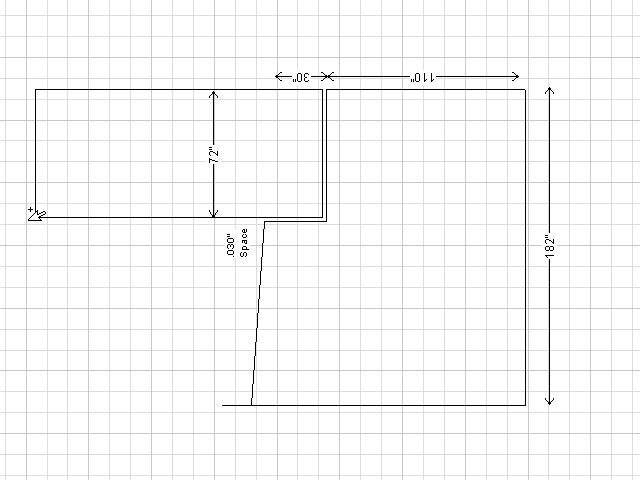
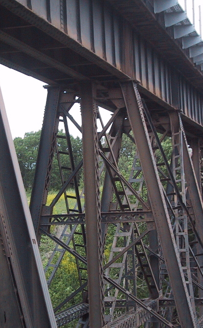
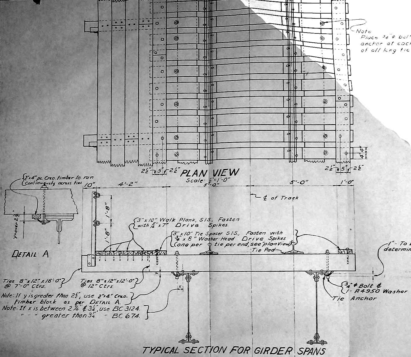
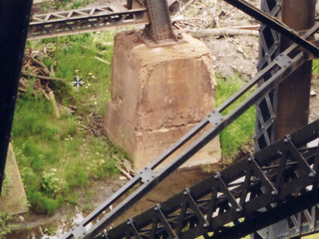
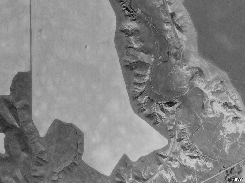
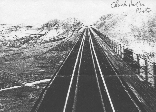
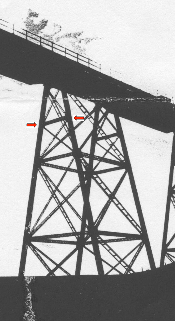
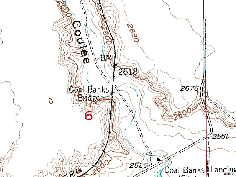
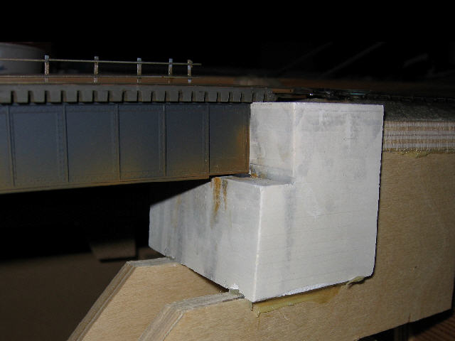
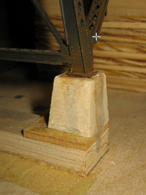
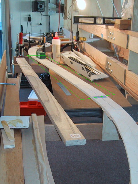
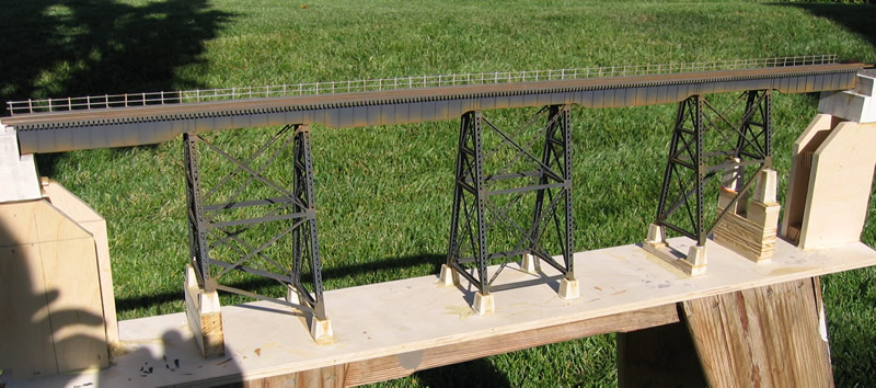
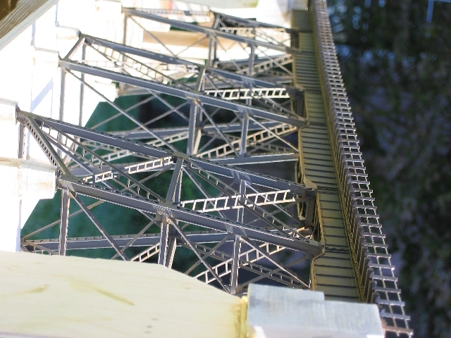
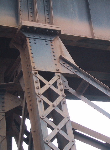
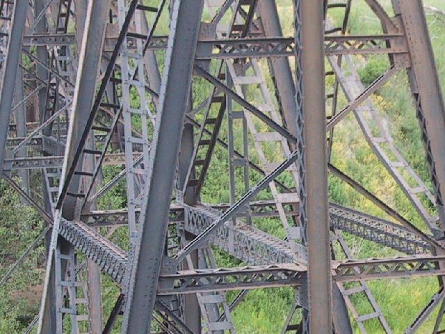
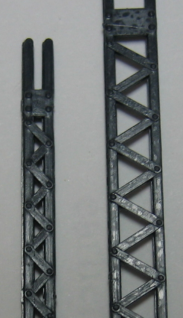
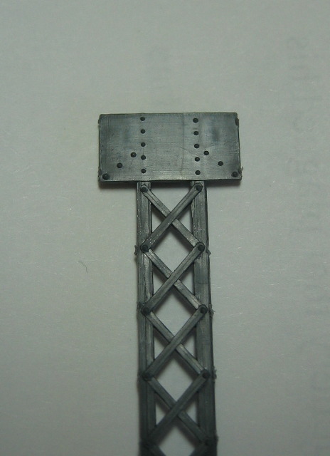
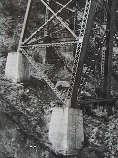
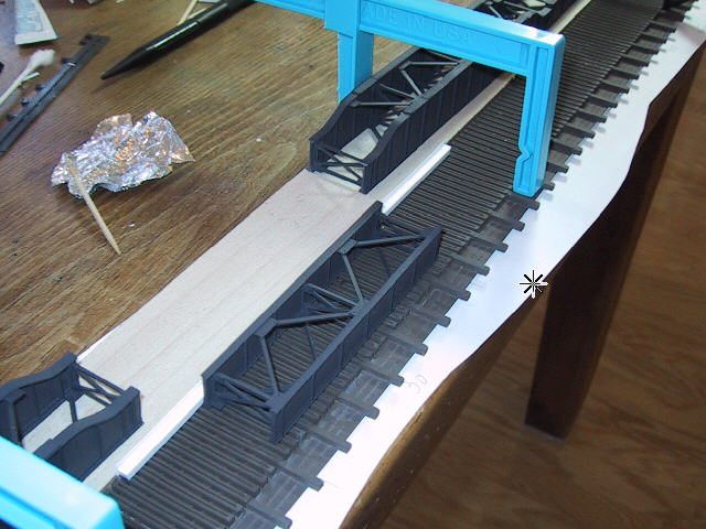
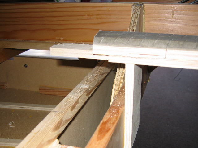
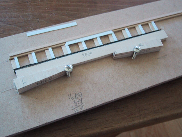
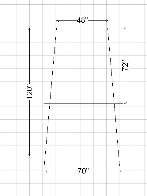
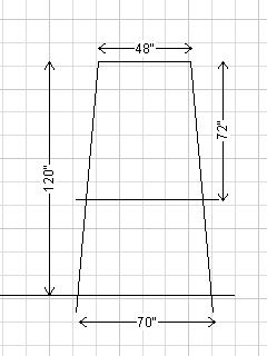
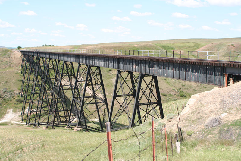
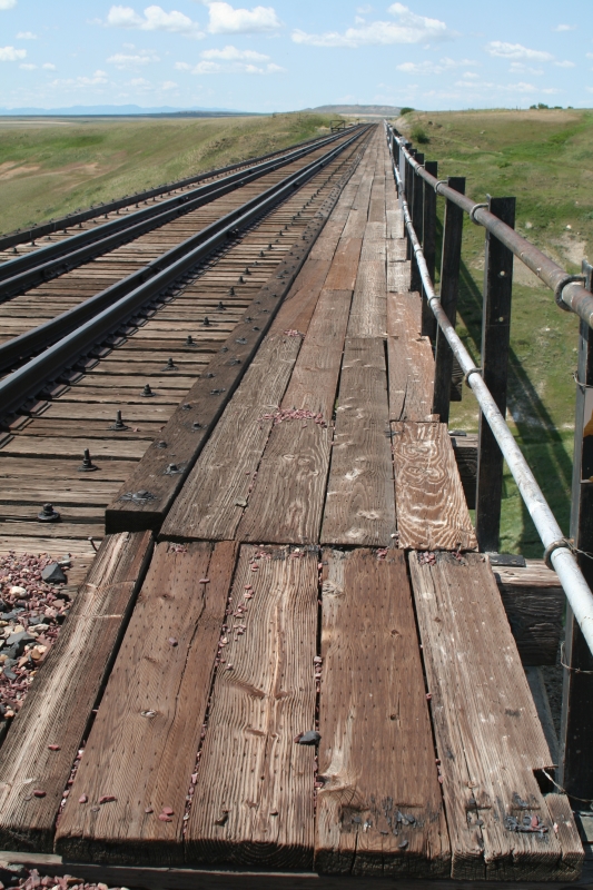
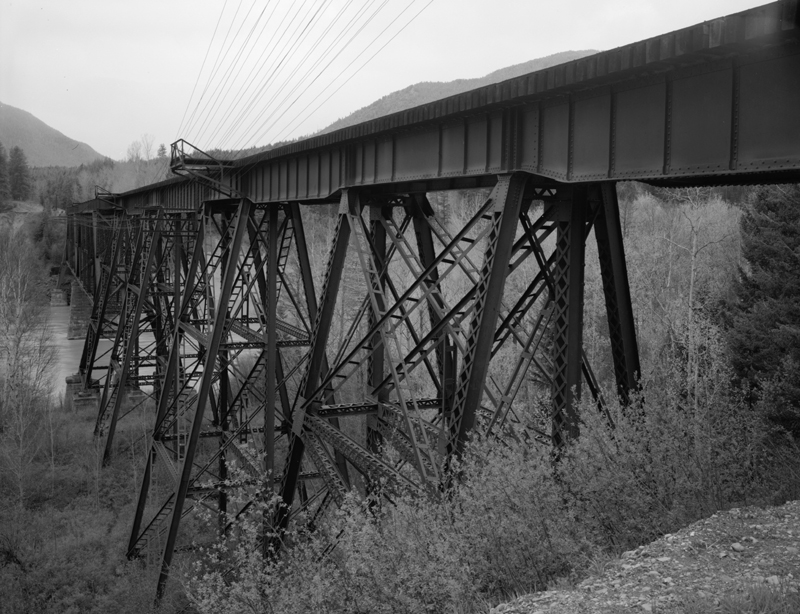
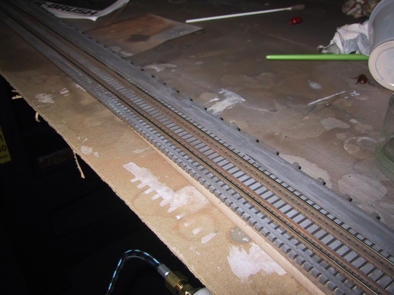
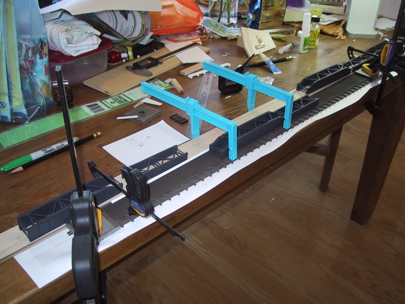
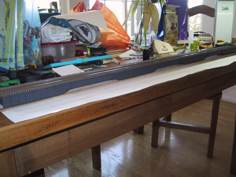
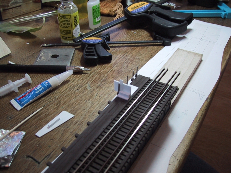
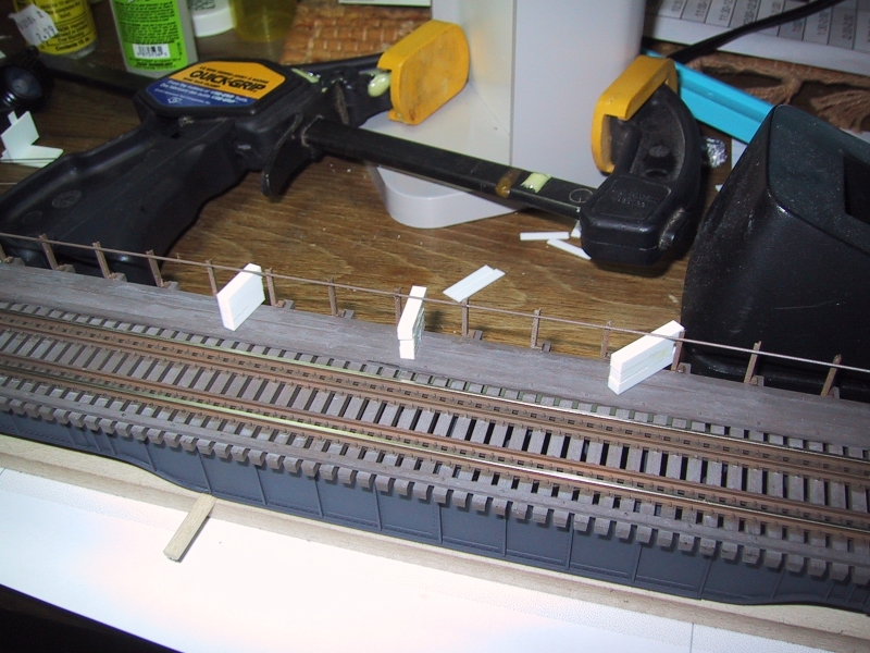
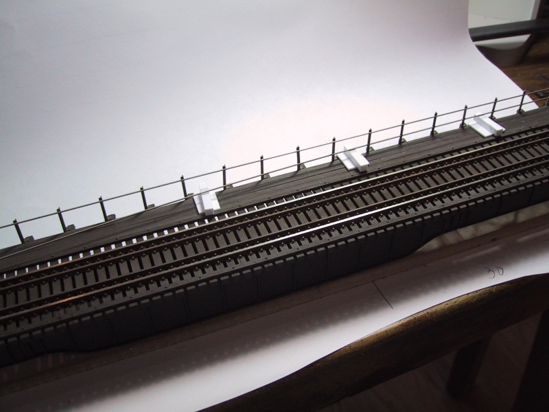
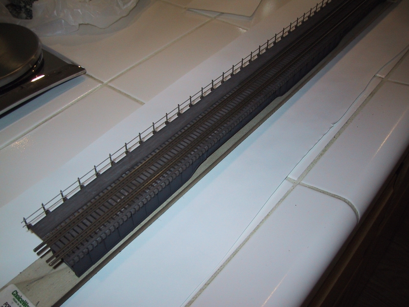
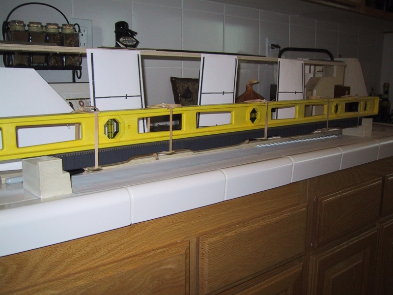
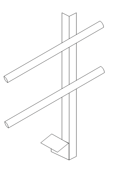
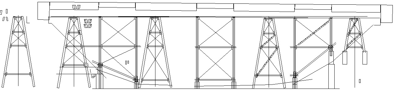
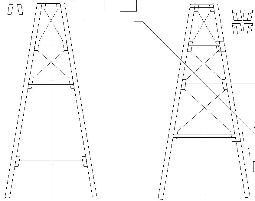
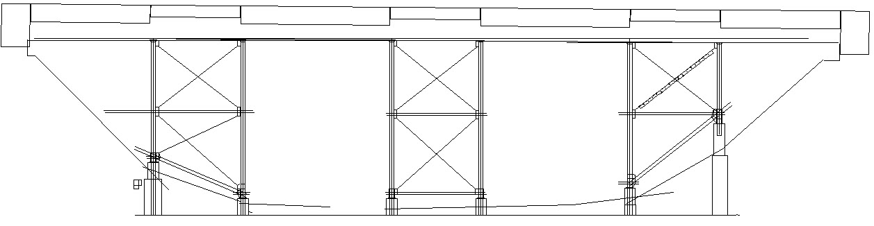
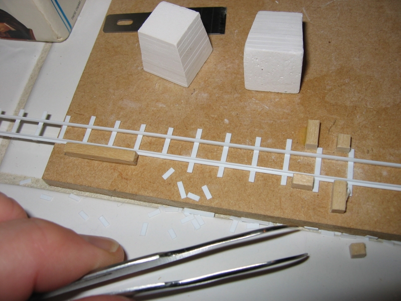
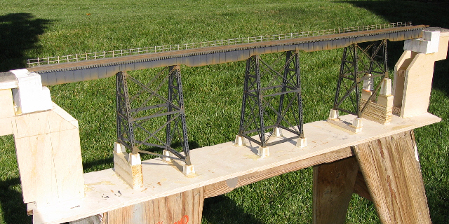
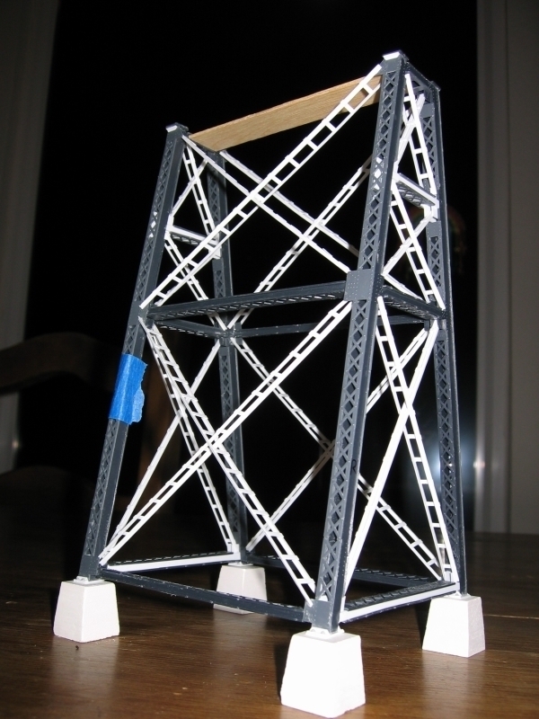
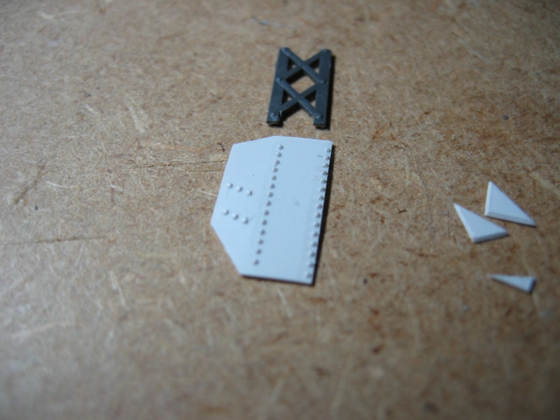
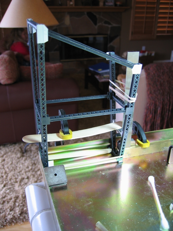
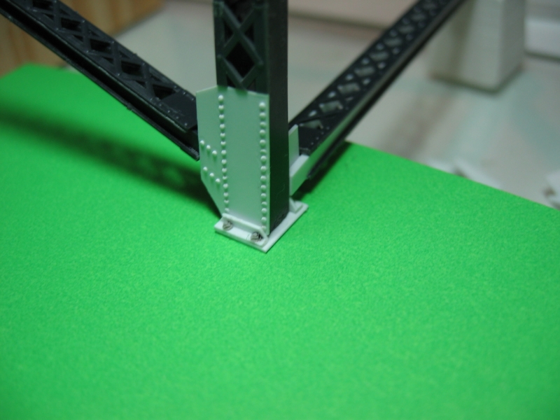
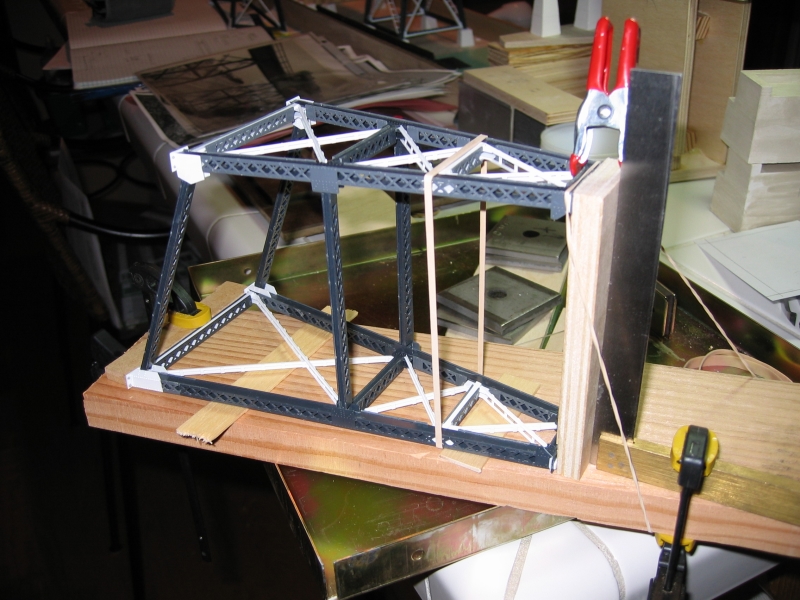
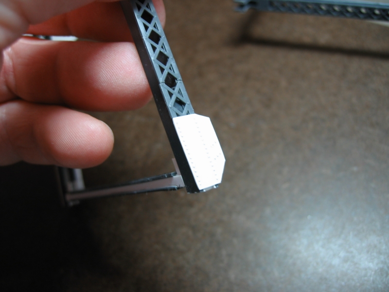
GreatNorthernFan
Confessions of a Great Northern Railway junkie.
  • Home
  • Prototype Inspiration
  • Layout Design
    • Trackplan
    • Trackplan Schematic
    • Double-Sided Shelf Design
    • Suspended Layout
      • Hoist
  • Construction
  • Models
  • Galleries
  • Resources
  • About
  • Contact
Browse: Home / Galleries

Galleries

  • All »
  • Coal Banks Trestle
Ready to install but who can resist taking a few glamour shots? Here is a closeup of a finished tower. Here is an assembled tower with the sway bracing in place. Pretty cool! Another example of custom bent cross supports. This one was needed as the height of the bent was customized for the terrain. Here is an assembled tower with the sway bracing in place. Pretty cool! GN Trestle sway braces had a ladder like design. The trestle towers are glued to the inverted girder and track assembly. Here is the finished model installed into my layout, ready for installation of the approach tracks. The bridge abutment and bent piers are attached with quick setting epoxy The bridge span is glued into position with the tower legs essentially unsupported. A few cans of vegetables worked great to hold the trestle steady while the epoxy under the foundation piers set. Here is my finished abutment casting. Abutment measurements I used on my model. abutment_design_icn Closeup photo of the Midvale Creek bridge near East Glacier, MT. bidge_track This is a portion of a GN standard drawing for a bridge trestle deck. bridge-xsection_sm GN Bridge trestle tower footings varied from cut stone to cast concrete, depending on the materials available and the era of construction. This example is the Midvale Creek bridge near East Glacier. This photo shows the removable bridge frame before the roadbed is cut. You can see I was test fitting the girders and also pasted mock-up of the trestle towers. Here is a shot of the model as it is being fitted to the removable frame. Notice the stiffeners along the base of this framework. bridge_opening bridge_opening2 bridge_railing caol_banks_arial This is the view for an engineer of Coal Banks trestle heading westbound. Photo: Chuck Hatler The Coal Banks trestle as it was being torn down. Photo Credit: Arndt coal_banks_profile2 The Coal Banks bridge spans a Coal Banks coulee as the GN line rises from the bank of the Missouri River to the plateau of the Montana plains in it’s way to Big Sandy, MT. Here is a finished abutment installed on the layout before finishing the scenery. finished_pier Roadbed was constructed through the bridge area as if there was not going to be a bridge. The green box indicates where the bridge will eventually be built. GN Span girders are tapered to match the height of the tower spans. gn_sway_braces This is the finished Coal Banks trestle model before installation into  my layout. img_0623_sm img_0649_sm img_0676_sm2 This GN bridge in Montana has a mix of solid and lattice bent facings. img_1659_sm The GN trimmed this gusset plate instead of leaving it square as in the ME casting. img_4333_sm img_4336_sm img_4351_sm img_4360_sm Closeup photo of the Midvale Creek bridge near East Glacier, MT. me_sway_braces The ME casting is a square gusset. me_trestle_tower Here are some more examples of piers on a GN bridge in Montana. Add picture of cut bank abutment here and tall pier. span_attach Support tabs are glued where the span roadbed is cutout to support the completed bridge framwork. This jig is used to hold the bridge tie extensions in position while the walkway board are glued. Pier measurements I used on my model. trestle_pier_icn A small personal vibrator was used to take the pain out of removing bubbles from the casting pour. North Fork Portage Coulee Trestle. North Fork Portage Coulee Trestle near Floweree, MT. Here is another example of the typical GN practice of tapering the girder spans to match the tower span. This is a key modification to make to the ME stock spans to achieve that GN look. img_4286_small The work is held with the master part to move against the milling bit together. The work is held with the master part to move against the milling bit together. The master is used to guide the part against the Dremel cutting bit. Here is another view of the jig I built to mill out the span taper. The webbing is first glued to the main part of the span. Here is a completed span modified with the tapered ends commonly seen on the GNRY. Walthers bridge track is my starting point for the bridge deck. Walthers bridge track is my starting point for the bridge deck. Walthers bridge track is my starting point for the bridge deck. This simple jig hold the bridge tie extension in alignment so the decking can be glued in place. This underside view of the completed deck walkway assembly fits right into the edge of the Walthers bridge track. The bridge deck walkway is attached as a single assembly to the edge of the Walthers bridge track. The railing post assembly are constructed of two pieces of styrene angle stock. Once again a jig is employed to hold the pieces in proper alignment for gluing. Tape was used to hold the tiny parts for painting. Painting improves the appearance of the Walthers track dramatically and bleds in the added walkway making it all work together. The white accrylic wash brings out details and lightens the overall color and provides a weathered appearance. I clamped the inverted track against the table and straight edge to allow focusing on the position of the spans as they are glued in position. The completed track and girder assembly. One more jig was constructed to align the railing posts for gluing. Plastic blocks were used to hold the piano wire railing at the proper height for gluing. img_4369_small The completed railing results in a very delicate and convincing appearance. The track deck and girder assembly is protected and held in alignment with rubber bands around a plastic level. The railing post assembly are constructed of two pieces of styrene angle stock. I drew out a full size profile of the bridge to provide templates for building and customizing the bents for the coulee terrain. coal-banks-bent-profiles coal-banks-model-profile This jig was used to make the GN ladder style sway braces. bridge_model2 This photo of the an assembled and unpainted tower shows the custom sway braces in white. Notice how there are two widths with one direction fitting inside the other. The resulting plates are just a hair bigger than we would like but overall look pretty good in the scale of the model. The patterned platic is embossed with the NSWL riveter. The NWSL Reveter tool is essential for creating simulated rivets. The platform is adjusted with a micrometer like device that allows precise control over spacing. A custom bent brace was needed to more closely match the GN prototype practice. The top rivet plates on the stock ME bents are trimmed to an angle to better match GN practice. The bent assembly requires all kinds of jerry-rigging to assure squareness and tightness of the joint. The irregular shapes of the custom height bents only adds to what is already probably the hardest step in the ME model assembly. Foundation bolt casting and angles were added to improve the mounting detail at the bottom of the bents. Here is another flavor of the rigging I used to hold the tower assemblies in place. Custom rivet plates were needed to accommodate custom cross brace angles.
[Show picture list]

Leave a Reply

About This Site

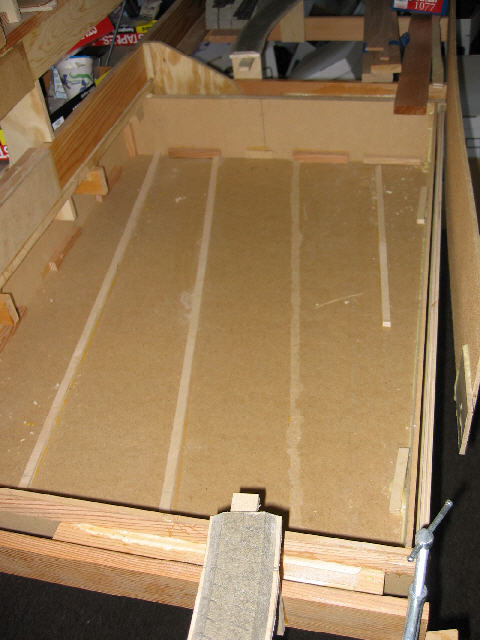
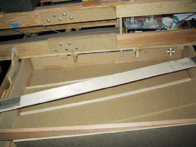
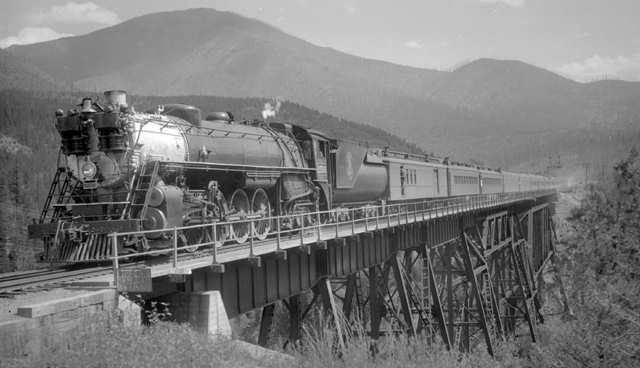
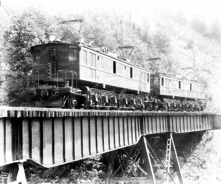
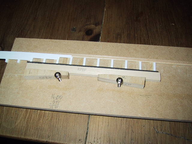
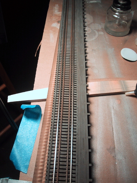
Welcome to Great Northern Fan. This site documents my model railroad project and also serves as an outlet to share my collection of historical images of the Great Northern Railway and sister roads.

Random Gallery Samples

file0007.jpg This is the Ft. Benton grain elevator. The bridge abutment and bent piers are attached with quick setting epoxy Here is my finished abutment casting.

Search

Copyright © 2025 GreatNorthernFan.

Powered by WordPress and Hybrid.